Monday, February 20, 2017

Openvpn - Ipfire setup


Archive of setup web page

Table of Contents

Introduction

This tutorial is a follow-up to the Install IPFire Linux Firewall tutorial. The goal is to configure OpenVPN from inside IPFire to support a client-to-network or host-to-net configuration. This can also be referred to as a "road warrior" configuration. It is most often used when you would like to establish a secure connection into the private network from various remote locations. This is in contrast with a network-to-network (site-to-site) configuration where you are linking two private networks that are each protected by IPFire or OpenVPN servers.

Requirements

Complete part one of the tutorial OR have an available IPFire virtual machine configured in your data center.
Access to the IPFire web interface. (Typically listens on port 444)
Optional: SSH access to the IPFire server. (Typically listens on port 222)

Configure OpenVPN on the IPFire Server

Open Services -> OpenVPN from the top navigation menu once you have logged in as admin.
OpenVPN Services Menu
Click Generate root/host certificates.
OpenVPN Services Main Screen
Fill out the required fields Organization Name and IPFire's Hostname. The hostname should be populated automatically. 2048 is a reasonable value to select from the Diffie-Hellman parameters length drop-down menu.
OpenVPN Generate Certificates
The WARNING in the screenshot above is valid. Generating the root and host certificate can take a long time. If you want to confirm that it is working, open a SSH session to the IPFire server and use the top command to see the openssl process running with significant %CPU activity while the certificates are being generated. The certificate generation process took 10 - 15 minutes to complete for this tutorial.
OpenVPN Generate Certificates top
You will be returned to the Services -> OpenVPN screen once the certificates have been generated. The Certificate Authorities and Keys section will contain new values for Subject and Action.
Click Advanced Server Options.
OpenVPN Generate Certificates done
Under Advanced server options you can select SHA2 (256 bit) for the Hash algorithm and also check the box for HMAC tls-auth. Use the Save advanced options button when you are done.
OpenVPN Advanced Options
Now check the boxes for OpenVPN on RED and LZO-Compression and then press the Save and Start OpenVPN Server buttons. We want to have OpenVPN listening on the "RED" interface so we can establish an OpenVPN connection across the public internet. The "LZO-Compression" option reduces bandwidth usage by compressing traffic that passes over the VPN.
OpenVPN Start
The OpenVPN server will start and this will be reflected by the value of Current OpenVPN server status changing from STOPPED to RUNNING.
OpenVPN Started

Verification

Now that OpenVPN has started, you can verify it is listening on port 1194 from the shell using netstat.
[root@ipfire ~]# netstat -na |grep 1194
udp        0      0 0.0.0.0:1194            0.0.0.0:*
or using ss with the -u for UDP and -l for LISTEN options, like this:
[root@ipfire ~]# ss -u -l |grep openvpn
State      Recv-Q Send-Q                 Local Address:Port          Peer Address:Port
UNCONN     0      0                       *:openvpn                  *:*

Add a User

In the Connection Status and -Control section, press the Add button to begin the process of adding a new user.
Connection Status Control Add
The Host-to-Net Virtual Private Network (Roadwarrior) connection type should be selected by default. Confirm the selection and press Add to continue.
Connection Status Control Add Host-to-Net
We will now complete the fields on this screen. Under Connection: we need to fill out Name:. You may wish to add a Remark: as a comment or note to yourself regarding who this user is. Please make sure Enabled: is checked.
Under Authentication: we want to Generate a certificate: so we will need to enter the User's full name or system hostname: and enter a password in the PKCS12 File Password fields. The Valid till (days) field controls the expiration date of the certificate. If your organization doesn't have to comply with any specific regulations regarding certificate replacement, then entering a value of 999 gives this user a little under three years until expiration.
Connection Status Control Add Host to Net User Details
For this tutorial, we will ignore the Advanced client options section. Additional details on the various configuration options available here can be found in the OpenVPN client config section of the IPFire Wiki.
When you have the necessary fields filled out, press the Save button.
NOTE: Keep track of the PKCS12 File Password assigned here as the client will need it to connect.
The Connection Status and -Control section of Services->OpenVPN should now show the newly-added user.
Connection Status Control New User

Download and Install the OpenVPN Client Software

The OpenVPN client can be downloaded from OpenVPN.net
You will want to choose the appropriate installer for the OS you are installing on. For Windows 10 64-bit, you would select the "Installer (64-bit) Windows Vista and Later". At the time of writing, the file you would end up downloading is called openvpn-install-2.3.8-1601-x86_64.exe. Be aware that this filename will change as new versions of the OpenVPN client software are released.
Once you have the installer file downloaded, go ahead and start the installation. The installation process on Windows 10 is quite typical with one exception. During the install you will be prompted to approve the installation of the 'device software' "TAP-Windows Provider V9 Network adapters"
TAP Network Adapter Prompt
Click the Install button to approve the installation and continue.
After a few minutes, you should see a screen indicating that the installation has completed successfully.
OpenVPN client install completed successfully
At this point, I would suggest that you do NOT launch the software, but instead take a look through the README file. For version 2.3.8, the following important information is contained in the INSTALL-win32.txt file:
Finally, install the new version of OpenVPN and copy over
your configuration files and certificates, which now go to

    C:\Program Files\OpenVPN\config

provided you did not install the 32-bit version on 64-bit
Windows.

IMPORTANT NOTE FOR WINDOWS VISTA/7 USERS

Note that on Windows Vista, you will need to run the OpenVPN
GUI with administrator privileges, so that it can add routes
to the routing table that are pulled from the OpenVPN server.
You can do this by right-clicking on the OpenVPN GUI
desktop icon, and selecting "Run as administrator".
We will follow that advice and copy the configuration files to our local system and put them in the appropriate directory.

Client Configuration

The config files are available in a zip archive which can be downloaded from the ipfire web interface.
OpenVPN download client package
Use the Download Client Package (zip) action icon to save a copy of the config files to your local system.
OpenVPN download client package save
Once the file is downloaded, extract the contents to a temporary location and we will proceed to copy the files to the correct location. For this tutorial there are three files in the zip archive:
JDoe.p12
JDoe-TO-IpFire.ovpn
ta.key
Here is a screenshot of the default config directory C:\Program Files\OpenVPN\config on Windows 10 (64-bit):
OpenVPN default config directory
We need to provide administrator permissions in order to copy the files into the config directory successfully.
OpenVPN config directory needs administrator permissions
Once the files have been copied in, you should have something similar to the following:
OpenVPN config directory
Finally we can connect to OpenVPN by launching the OpenVPN GUI with "Administrative Permissions". To do this, right-click the "OpenVPN GUI" shortcut or menu item, go to "More" and then "Run as administrator". Press the Yes button when the "User Account Control" warning pops up.
OpenVPN GUI launch as administrator
The OpenVPN GUI icon should appear in your task bar. Right-click it and you should see the options available, including one to Connect.
OpenVPN GUI connect
If the configuration files are NOT present, the menu is much shorter. So, if you happen to see something like this:
OpenVPN GUI connect no config
then double-check that you have copied the configuration files into the correct location.
When we Connect, we will be prompted for the PKCS12 File Password that we set earlier when adding the Host-to-Net user. Enter it now, and some information will scroll by as the connection is established.
OpenVPN GUI connecting
If successful, we will briefly see a notification in the lower right corner of the screen:
OpenVPN GUI connected
The OpenVPN GUI taskbar icon has changed to a green color indicating a successful active connection. If you want to see the status of your connection, you can right-click the taskbar icon and select Show Status from the menu.
OpenVPN GUI connected show status
Everything looks good, so we can proceed to test the connection. How you do this will somewhat depend on what other resources you have configured on your data center network. At the very least though, we should now be able to ping the GREEN network interface of the IPFire server from our local machine that is now connected via OpenVPN.
C:\>ping 172.16.1.1

Pinging 172.16.1.1 with 32 bytes of data: 
Reply from 172.16.1.1: bytes=32 time=43ms TTL=64
Reply from 172.16.1.1: bytes=32 time=44ms TTL=64
Reply from 172.16.1.1: bytes=32 time=43ms TTL=64
Reply from 172.16.1.1: bytes=32 time=44ms TTL=64

Ping statistics for 172.16.1.1:
    Packets: Sent = 4, Received = 4, Lost = 0 (0% loss),
Approximate round trip times in milli-seconds:
    Minimum = 43ms, Maximum = 44ms, Average = 43ms
We should also be able to access the IPFire web interface over the GREEN network (https://172.16.1.1:444) via the VPN instead of having to access it over the RED network.

Troubleshooting

If you are having difficulty connecting to resources on the private network over the OpenVPN connection there are a few things you can check.
The OpenVPN client needs elevated permissions in order to modify the Windows system routing table. If your traffic is not being routed properly, make sure that you launched the OpenVPN client/GUI with Administrator permissions. Generally this is done by right-clicking the icon for the program and choosing "Run as administrator".
Make sure the appropriate route has been added so that you can access the private network from your OpenVPN client. If you are running the OpenVPN client on Windows, you can use netstat -nr to take a look at the system routing table.
===========================================================================
Active Routes:
Network Destination        Netmask          Gateway       Interface  Metric
          0.0.0.0          0.0.0.0     192.168.10.1   192.168.10.246     10
      10.71.202.1  255.255.255.255      10.71.202.5      10.71.202.6     20
      10.71.202.4  255.255.255.252         On-link       10.71.202.6    276
      10.71.202.6  255.255.255.255         On-link       10.71.202.6    276
       172.16.1.0    255.255.255.0      10.71.202.5      10.71.202.6     21
The last entry in the table above shows that traffic destined for the 172.16.1.0/24 network will be routed through 10.71.202.5 to the IPFire server running OpenVPN. This will allow us to access any servers using an IP address in the 172.16.1.0/24 ip range, including the management interface of IPFire itself. For the tutorial, we have IPFire listening on 172.16.1.1:444.
The route(s) the server automatically pushes to the client when connecting are controlled by an individual CCD (Client Configuration Directive) file on the server. These files are stored in /var/ipfire/ovpn/ccd/ with a filename that matches the user we added. For purposes of this tutorial, the full path to the file is /var/ipfire/ovpn/ccd/jdoe. If we take a look at that file, we can see that a route for our private 172.16.1.0/24 network is properly configured to be pushed to the connecting OpenVPN client.
[root@ipfire ccd]# more jdoe
# OpenVPN clientconfig from ccd extension by Copymaster#

#This client uses the dynamic pool

#Client gets routes to these networks (behind IPFire)
push "route 172.16.1.0 255.255.255.0"
You may find that a different route is set here if you have changed the ip network the GREEN/Private interface is using since initially configuring OpenVPN or adding the user.

Support

You are welcome to post questions or comments related to this tutorial and we will endeavor to provide assistance.

Wednesday, February 15, 2017

Launching vmware clients on Linux host using VMware VIX libraries


How to launch VMware Player VMs without GUI

If you are a user of VMware Player, you may have wondered whether it's possible to run VMware player without GUI. For example, when you are accessing VMware hosts via SSH remotely, you may want to run VMware Player from the command line.

 While you can use X11 forwarding over SSH to launch VMware player's GUI from remote locations, it will be rather inconvenient if the SSH connection is slow. Furthermore, the VM launched inside VMware Player's GUI window will automatically be stopped when you close the VMware Player window.

If you would like to start or stop VMware Player VMs without GUI, you can use vmrun which is a command-line utility which one can use to automate operations on VMware virtual machines (VMs). vmrun is contained in VMware VIX API libraries which are freely downloadable from VMware website. You can follow the instructions below to manage VMware Player VMs remotely.

It is assumed that you have already created a VM using VMware Player, and so have *.vmx files ready somewhere. Now you want to start/stop the VM using vmrun. You don't need root permission to use vmrun command.

First, download VMware VIX for Linux, and then install it on the VMware host as follows.
$ chmod 755 ./VMware-VIX-1.11.0-471780.x86_64
$ sudo ./VMware-VIX-1.11.0-471780.x86_64
 
To start VM:
$ vmrun -T player start /path/to/vm/my.vmx nogui
 
To reboot VM:
$ vmrun -T player reset /path/to/vm/my.vmx soft
 
To power off VM:
$ vmrun -T player stop /path/to/vm/my.vmx soft


Tuesday, February 7, 2017

Saturday, January 28, 2017

Attachments banned by google


Routine attachment extensions banned by Google.  If the are going to be attached, they will need to be renamed and hidden.  Usual method is to create either a tgz or zip file containing the files, and then rename that attachment.  Usual that seems to work is to reverse the spelling of the file.

So far google doesn't seem to vet the attachment with the "file" type as well as the extension, because presumably software at the receiving or download end ignores it if the extension doesn't match.

http://www.computerworld.com/article/3161898/security/gmail-will-block-javascript-attachments-a-common-source-of-malware.html

Users will no longer be able to attach .JS files to emails in Gmail, regardless of whether they attach them directly or they include them in archives like .gz, .bz2, .zip or .tgz. For those rare cases when such files need to be shared via email, users can upload them to a storage service like Google Drive and then share the link.
The .JS file extension will be added an existing list of other banned file attachments that includes: .ADE, .ADP, .BAT, .CHM, .CMD, .COM, .CPL, .EXE, .HTA, .INS, .ISP, .JAR, .JSE, .LIB, .LNK, .MDE, .MSC, .MSP, .MST, .PIF, .SCR, .SCT, .SHB, .SYS, .VB, .VBE, .VBS, .VXD, .WSC, .WSF and .WSH. Most of these file types have long been abused by cybercriminals to send malware via email.

Thursday, January 26, 2017

USB drives on VMware ESXI6 servers


http://www.virten.net/2015/10/usb-devices-as-vmfs-datastore-in-vsphere-esxi-6-0/

Information archived below:

USB Devices as VMFS Datastore in vSphere ESXi 6.0

In the last years I've seen many requests in forums and blogs where people are trying to use USB devices like USB sticks or external hard disks as VMFS formatted datastore. It was actually possible in vSphere 5, but very picky. Some USB flash drives were working, others not. In vSphere 6, this behavior has been changed obviously. This post explains how you can use USB devices as datastore on your ESXi host. Of course, this is neither a supported, nor a performant storage solution, so use at your own risk.
[Update: If you are looking for USB VMFS Datastores in vSphere 6.5, read this article.]

Create VMFS Datastore on USB drives

  1. Connect to the ESXi host with SSH
  2. Stop the USB arbitrator service. This service is used to passthrough USB device from an ESX/ESXi host to a virtual machine. (When disabling it, you can no longer passthrough USB devices to VMs)
    ~ # /etc/init.d/usbarbitrator stop
  3. (optional) Use this command to permanently disable the USB arbitrator service after reboot.
    ~ # chkconfig usbarbitrator off
  4. Plug in the USB Device to your ESXi host
  5. Get the device identifier (mpx.vmhbaXX). You should see the USB Device in /dev/disks/:
    ~ # ls /dev/disks/
  6. Write a GPT label to the device (Assuming that the Device ID is mpx.vmhba36)
    ~ # partedUtil mklabel /dev/disks/mpx.vmhba36\:C0\:T0\:L0 gpt
  7. To create a partition you need to know the start sector, end sector, which depends on the device size and the GUID.
    The start sector is always 2048
    The GUID for VMFS is AA31E02A400F11DB9590000C2911D1B8
    The end sector can be calculated with the following formula (Use the numbers from getptbl):
    ~ # partedUtil getptbl /dev/disks/mpx.vmhba36\:C0\:T0\:L0
    gpt
    1947 255 63 31293440
    1947 * 255 * 63 - 1 = 31278554
    You can also calculate the endsector with the following command:
    ~ # eval expr $(partedUtil getptbl /dev/disks/mpx.vmhba36\:C0\:T0\:L0 | tail -1 | awk '{print $1 " \\* " $2 " \\* " $3}') - 1
    31278554
  8. Create the VMFS partition (Replace with your endsector)
    ~ # partedUtil setptbl /dev/disks/mpx.vmhba36\:C0\:T0\:L0 gpt "1 2048 31278554 AA31E02A400F11DB9590000C2911D1B8 0"
  9. Format the partition with VMFS5
    ~ # vmkfstools -C vmfs5 -S USB-Stick /dev/disks/mpx.vmhba36\:C0\:T0\:L0:1
The USB-Stick should now appear in your datastores view.
vmfs-formatted-usb-stick
And the final proof is a virtual machine running on it:
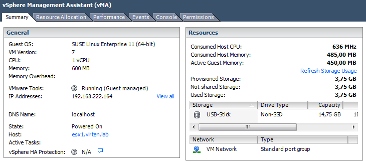
vm-running-on-usb-stick
This is how your command output should look like:
~ # partedUtil mklabel /dev/disks/mpx.vmhba43\:C0\:T0\:L0 gpt
~ # eval expr $(partedUtil getptbl /dev/disks/mpx.vmhba43\:C0\:T0\:L0 | tail -1 | awk '{print $1 " \\* " $2 " \\* " $3}') - 1
31278554
~ # partedUtil setptbl /dev/disks/mpx.vmhba43\:C0\:T0\:L0 gpt "1 2048 31278554 AA31E02A400F11DB9590000C2911D1B8 0"
gpt
0 0 0 0
1 2048 31278554 AA31E02A400F11DB9590000C2911D1B8 0
~ # vmkfstools -C vmfs5 -S USB-Stick /dev/disks/mpx.vmhba43\:C0\:T0\:L0:1
create fs deviceName:'/dev/disks/mpx.vmhba43:C0:T0:L0:1', fsShortName:'vmfs5', fsName:'USB-Stick'
deviceFullPath:/dev/disks/mpx.vmhba43:C0:T0:L0:1 deviceFile:mpx.vmhba43:C0:T0:L0:1
ATS on device /dev/disks/mpx.vmhba43:C0:T0:L0:1: not supported
.
Checking if remote hosts are using this device as a valid file system. This may take a few seconds...
Creating vmfs5 file system on "mpx.vmhba43:C0:T0:L0:1" with blockSize 1048576 and volume label "USB-Stick".
Successfully created new volume: 56226b60-118f2e3f-04ba-001b2193b3b0


[Update: October 19. 2015 - Figured out why devices are detected as USB 2. Devices now with full USB 3.0 performance. Performance test results updated.]
 
http://www.virten.net/2015/10/usb-3-0-devices-detected-as-usb-2-in-esxi-6-0-and-5-5/ 

USB 3.0 devices detected as USB 2 in ESXi 6.0 and 5.5

In my latest post USB Devices as VMFS Datastore in vSphere ESXi 6.0 I had a problem with USB 3.0 devices that are detected as USB 2 in ESXi. I know that USB 3.0, also known as eXtensible Host Controller Interface (xHCI), is supported in ESXi 6.0 and ESXi 5.5 Build 2143827 or later. Unfortunately all of my devices are detected as USB 2.1, despite the USB 3 hub was visible. This problem applies to both, USB devices in path-through mode, and USB devices mounted from the command line with usbarbitrator disabled. The solution was quite simple and not related to an ESXi, but to a UEFI configuration.
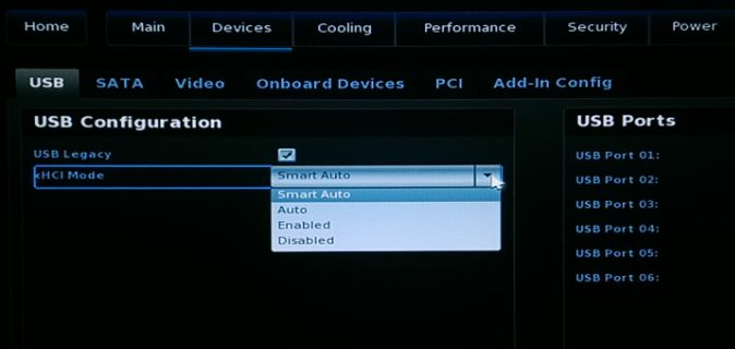
xhci-smart-auto

Within the UEFI the xHCI mode is configurable with a default of "Smart Auto". According to the documentation, in "Smart Auto" mode the USB 3.0 port acts like a 2.0 port before OS USB 3.0 drivers are loaded. For whatever reason, this does not work properly with ESXi. After setting xHCI Mode to "Enabled", all devices are correctly identified as USB 3.0.
During my tests I've use two USB 3.0 capable devices on my 5th Gen Intel NUC (NUC5i5MYHE):
  • External 1TB 2.5" HDD (Seagate RSS LLC FreeAgent GoFlex USB 3.0)
  • USB 3.0 to mSATA SSD Enclosure (ASMedia Technology Inc.)
ESXi 6.0 with xHCI Mode "Smart Auto"
Both devices are connected to "Bus 001", which is the 2.0 root hub:
~ # vmware -v VMware ESXi 6.0.0 build-3073146 ~ # lsusb Bus 001 Device 007: ID 0bc2:5031 Seagate RSS LLC FreeAgent GoFlex USB 3.0 Bus 001 Device 006: ID 174c:1153 ASMedia Technology Inc. Bus 001 Device 003: ID 0930:6545 Toshiba Corp. Kingston DataTraveler 102 Flash Drive / HEMA Flash Drive 2 GB / PNY Attache 4GB Stick Bus 001 Device 002: ID 8087:8001 Intel Corp. Bus 003 Device 001: ID 1d6b:0003 Linux Foundation 3.0 root hub Bus 002 Device 001: ID 1d6b:0002 Linux Foundation 2.0 root hub Bus 001 Device 001: ID 1d6b:0002 Linux Foundation 2.0 root hub ESXi 5.5 with xHCI Mode "Smart Auto"
Same problem here. Both devices on "Bus 001".
~ # vmware -v VMware ESXi 5.5.0 build-3116895 ~ # lsusb Bus 001 Device 008: ID 0bc2:5031 Seagate RSS LLC FreeAgent GoFlex USB 3.0 Bus 001 Device 007: ID 174c:1153 ASMedia Technology Inc. Bus 001 Device 003: ID 0930:6545 Toshiba Corp. Kingston DataTraveler 102 Flash Drive / HEMA Flash Drive 2 GB / PNY Attache 4GB Stick Bus 001 Device 002: ID 8087:8001 Intel Corp. Bus 003 Device 001: ID 1d6b:0003 Linux Foundation 3.0 root hub Bus 002 Device 001: ID 1d6b:0002 Linux Foundation 2.0 root hub Bus 001 Device 001: ID 1d6b:0002 Linux Foundation 2.0 root hub You can also use the lsusb -v command to see a verbose output containing the USB version (2.10):
~ # lsusb -v Bus 001 Device 008: ID 0bc2:5031 Seagate RSS LLC FreeAgent GoFlex USB 3.0 Device Descriptor: bLength 18 bDescriptorType 1 bcdUSB 2.10 bDeviceClass 0 (Defined at Interface level) [...] Bus 001 Device 007: ID 174c:1153 ASMedia Technology Inc. Device Descriptor: bLength 18 bDescriptorType 1 bcdUSB 2.10 [...] The problem described here applies only if you see a USB 3.0 root hub but devices are connected to the wrong hub. If you do not see the USB 3.0 hub you have to verify that the xhci module is enabled and loaded with:
~ # esxcli system module list |grep xhci Name Is Loaded   Is Enabled xhci true true To enable it (Load it automatically on boot):
~ # esxcli system module set -e true -m xhci To load it while ESXi is running:
~ # vmkload_mod xhci xHCI Mode "Enabled"
After setting the xHCI Mode to "Enabled" in the UEFI, both devices are connected to the USB 3.0 hub:
~ # vmware -v VMware ESXi 5.5.0 build-3116895 ~ # lsusb Bus 002 Device 002: ID 174c:1153 ASMedia Technology Inc. Bus 002 Device 004: ID 0bc2:5031 Seagate RSS LLC FreeAgent GoFlex USB 3.0 Bus 001 Device 002: ID 0930:6545 Toshiba Corp. Kingston DataTraveler 102 Flash Drive / HEMA Flash Drive 2 GB / P Attache 4GB Stick Bus 002 Device 001: ID 1d6b:0003 Linux Foundation 3.0 root hub Bus 001 Device 001: ID 1d6b:0002 Linux Foundation 2.0 root hub ~ # vmware -v VMware ESXi 6.0.0 build-3073146 ~ # lsusb Bus 002 Device 002: ID 174c:1153 ASMedia Technology Inc. Bus 002 Device 004: ID 0bc2:5031 Seagate RSS LLC FreeAgent GoFlex USB 3.0 Bus 001 Device 002: ID 0930:6545 Toshiba Corp. Kingston DataTraveler 102 Flash Drive / HEMA Flash Drive 2 GB / PNY Attache 4GB Stick Bus 002 Device 001: ID 1d6b:0003 Linux Foundation 3.0 root hub Bus 001 Device 001: ID 1d6b:0002 Linux Foundation 2.0 root hub lsusb -v Bus 002 Device 003: ID 174c:1153 ASMedia Technology Inc. Device Descriptor: bLength 18 bDescriptorType 1 bcdUSB 3.00 [...]

Tuesday, January 17, 2017

copying with rsync and progress info


when copying there is no way with copy to show progress / performance, so one cannot tell if a link is useless or not.

Use Rsync instead

This link with some info copied below shows a method

rsync -r --info=progress2 ./path directory /containing path directory
 -or-
rsync --progress -a sourceDirectory destinationDirectory

This will produce a copy, but add in progress bars showing amount complete, as well as rate information.

No notes on how to transfer a single file by this method, if including path is needed.  Will add that later

http://unix.stackexchange.com/questions/65077/is-it-possible-to-see-cp-speed-and-percent-copied


xx