http://www.raspberrypi-spy.co.uk/2014/11/how-to-create-a-raspberry-pi-video-capture-unit-part-1/
One hundred and fifty posts later I decided I should
really complete a project I’ve been thinking about ever since I got my
first Pi. That is a simple video capture unit that would be able to
record video, in a loop, with the minimum amount of hardware and setting
up.
I wanted a standard setup I could quickly deploy around the house,
garden, car or bike. The software needed to be easy to setup so I could
use it at short notice. I also wanted it to be basic enough that someone
else could use it as a basis for their own Pi camera projects.
This sort of idea isn’t exactly unusual and there are plenty of Pi
based camera projects out there but I wanted something I was happy with
and did exactly what I needed without any fancy features. Re-inventing
the wheel can be fun despite what other people might tell you!
Requirements
My requirements were something along these lines :
- Easy and quick to configure
- Basic Python script that is easy to follow
- Ability to define number and duration of video files to store
- Minimise hardware items
- Minimise wiring, soldering and construction time
- Provide a method to stop recording and correctly shutdown Pi
- Provide a quick method to attach to a tripod
- Provide a method to review footage on a PC
Although there are plenty of additional features I could have added I
wanted to keep this simple. So you won’t see WiFi, Bluetooth or any web
connectivity in this version.
Here is a photo of my finished system :

Hardware
The hardware I used is listed below :
- Raspberry Pi (Model B)
- Cyntech standard case
- 8GB SanDisk SD card
- 32GB Kingston Flash Drive
- Camera module
- 8mm metal washer
- 3D printed tripod mount
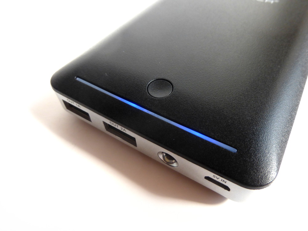
- RAVPower RP-PB13 14000mAh USB power bank

I needed 1 switch and 1 LED so used an already assembled
BerryClip add-on board.
This was a quick way of giving me an LED and Switch without me needing
to do any additional wiring. You can easily complete this project with
your own LED, switch and resistors wired up to the appropriate GPIO
pins. In order to fit everything in the case I need to drill holes to
accommodate the LEDs, buzzer and camera. The switch was recessed but
still usable.
Sticky pads were used to secure the camera in place. The metal washer was glued in place on the outside to allow
cheap magnetic lenses to be attached if required.
Tripod Mounting
In this project I used the Cyntech case as it is good value, easy to modify and has a nice Raspberry Pi logo on it. My friend
Graham
3D printed me a plastic insert which held a metal nut compatible with
my tripod. This beautifully simple modification makes the whole unit
easy to mount in a fixed position without having to balance it on piles
of books.
Usage
When the Pi is powered up a cron job is started which looks for a
network connection. If there is no network the main Python script is
run. I didn’t want the script to start when connected to a network as
this is when I wanted to download video without the camera being active.
The main script reads the configuration file and starts recording a
video file. The files can be saved onto the SD card or a USB flash
drive. When the pre-set duration is reached the file is closed and a new
one is started. If the total number of video files reaches a pre-set
limit then the oldest one is deleted. The device can continue recording
over-writing files as required.
The configuration file let’s you set the total number of files to
keep, the duration of each file as well as camera properties such as
frame rate and resolution.
When you are finished you can hold down the button to quit the script
and shutdown the operating system. The power can then be removed.
 Power
Around the house it is easy enough to use mains power but when I want to use the unit on the car or bike I just use my
Ravpower RP-PB13 14000mAh USB power bank. I’ve had this battery for a while now and it has been in fairly regular use in my household.
Car Mounting
With a windscreen mount from eBay it’s easy to create a simple dash cam!

Here are some additional photos :
Part 2 details the installation and setup procedure if you are interested in creating your own version.
How To Create A Raspberry Pi Video Capture Unit – Part 2
How To Create A Raspberry Pi Video Capture Unit – Part 2
Following on from
Part 1 I’ll explain how you can install the Python software and get your own Video Capture Unit up and running.
You don’t need to build your unit in exactly the same way as mine but as a minimum you need :
- Raspberry Pi
- SD card with Raspbian
- Camera module
- 5V power supply
- 1 LED attached to GPIO4 via current limiting resistor (ie 330 ohm)
- 1 Switch attached to GPIO7 with 10K pull-down to ground
If you want to be able to easily transfer video files to a PC you might also want to use a :
The setup might be spread over a desk or installed in
raspberry pi case. The choice is yours.

Software
The software is available from the
RPiSpy Video Capture Unit BitBucket repository and consists of the following main files :
- config.py
- cron.py
- instructions.txt
- prepare_mp4.bat
- prepare_mp4.sh
- vcu.py
config.py
This file contain the user defined settings used by vcu.py. It allows
the user to adjust various parameters. If “/boot/vcu_config.py” exists
it is copied over this config file. The vcu_config.py can be used to
edit settings on a Windows PC which can see the /boot/ partition on the
SD card.
cron.py
This script is run when the Pi boots. It looks for a network
connection and only runs vcu.py if it doesn’t find one. This allows the
Pi to boot normally when you have connected it to your network to copy
video files.
instructions.txt
Summary of these installation instructions for reference.
prepare_mp4.bat
This script provides an easy way to convert the recorded h264 files to
MP4 files. It may take a while to convert depending on the total
duration of the videos. It uses MP4Box and is meant to run via Windows.
prepare_mp4.sh
This script provides an easy way to convert the recorded h264 files to
MP4 files. It may take a while to convert depending on the total
duration of the videos. It uses MP4Box and is meant to run on the Pi
itself.
vcu.py
This is the main Python script which does most of the work. It is called from cron.py when the Pi boots.
Installation
First prepare a fresh SD card with Raspbian. Use a recent download from
the official RaspberryPi.org site. Why Raspbian? I use it for everything!
Power up the Pi and login. You will now be in the home directory.
Expand the file system and Enable the Pi Camera using the config tool :
sudo raspi-config
Ensure you’ve got the latest firmware using :
sudo rpi-update
Create a new directory and navigate into it :
mkdir rpispy_vcu
cd rpispy_vcu
Now we can download the archive file from BitBucket using :
wget https://bitbucket.org/MattHawkinsUK/rpispy-video-capture-unit/get/master.tar.gz
If you type
ls you should see the
master.tar.gz file sitting in the current directory. Use the following command to extract the files from the archive :
tar -xvf master.tar.gz --strip 1
Typing
ls should show you a list of the files :
You can remove the archive now using :
rm master.tar.gz
The Python scripts control the Raspberry Pi Camera Module using the
Picamera module. This is installed by default on the latest version of
Raspbian.
Then finally install MP4Box (aka gpac) which can be used to convert
the h264 files recorded by the camera to slightly more usable MP4 files :
sudo apt-get -y install gpac
Config File Setup (optional)
If you want to be able to edit the config file in Windows you will
need to place a copy in the /boot/ directory. You can do that using :
sudo cp config.py /boot/vcu_config.py
When the cron.py script runs at boot time it will check if there is a
vcu_config.py file in /boot/. If there is it copies it over config.py.
The main script would then run and use the new settings.
USB Flash Drive Setup
In order to save our video files to a removable drive we need to get
the Pi to automatically mount the USB flash drive. This is a fairly easy
process and is described in my
How To Mount A USB Flash Disk On The Raspberry Pi tutorial. Follow the tutorial so that your drive is mounted as “/media/usb”.
If you don’t want to use a USB flash drive and you want to store videos on your SD card you will need to make a directory :
mkdir ~/rpispy_vcu/videos
and set the VIDEO_PATH parameter in the config.py file to point to
‘/home/pi/rpispy_vcu/videos/’. Don’t forget to update
/boot/vcu_config.py if you are using that file.
Autorun On Boot Setup
To run the script automatically when the Pi boots you can use ‘cron’. To edit it we use the command :
sudo crontab -e
Using your cursor keys scroll to the bottom and add the following line :
@reboot python /home/pi/rpispy_vcu/cron.py &
Make sure you get this line correct as the script will fail to run on
boot if there are any mistakes. Note that it ends in an ampersand
symbol.
To save these changes click “CTRL-X”, then “Y” and finally “Return”. You should now be back at the command prompt.
First Run

Shutdown
your Pi and remove the power. Disconnect your network cable. Reconnect
the power and boot the Pi. The Pi will boot and you will hear the buzzer
sound once. The camera is now recording!
When you want to stop recording hold down the button until you hear a
double beep from the buzzer. The Pi will shutdown. Wait 10 seconds
before removing the power cable.
In part 3 I will cover converting the resulting video files into MP4
files which makes them easier to play in a media player or editing
application.
How To Create A Raspberry Pi Video Capture Unit – Part 3
How To Create A Raspberry Pi Video Capture Unit – Part 3
In
Part 1 and
Part 2
of this set of articles I explained how I made a simple video recording
device with the Raspberry Pi, a camera module and a plastic case. It’s
simple enough to be mounted wherever you need a video camera.
In this final part I will explain how I extract the resulting video
files from the unit and convert them to MP4 files. This makes them
easier to play on other devices and media software.
Converting The Files Directly On The Pi
To convert the files using the Pi you can use the “prepare_mp4.sh”
script. Plug the Pi into a network and power it up. We do not want the
Pi to start recording video but the main script will not run if a
network connection is detected.
The script uses MP4Box to do the conversion. If you haven’t installed it previously you can do so using :
sudo apt-get install gpac
Now you can navigate to the location where your video files are and
check a copy of the script is present. Run the “prepare_mp4.sh” script
using :
./prepare_mp4.sh
It may take a while but the h264 files in the directory will be
converted to MP4. You will need to make sure there is sufficient space
available to do this as you will end up with a h264 and MP4 file for
each clip.
Once the script has finished you can transfer the resulting video files via SSH or FTP to another computer.
Converting On A Windows PC
My preferred method is to write the video to a USB drive. This can
then be plugged into a PC and the “prepare_mp4.bat” script will then
convert the h264 files and give you a set of MP4s. In order to use this
method you will need to :
Your MP4 files will be prepared and saved in the “d:\temp” directory.
You can use a different directory but you will need to update the batch
file appropriately.
Your video capture unit is now ready for another adventure!
Example Video Footage
Here is a two minute compilation I created from footage I filmed while the camera was attached to my windscreen :
The camera resolution was set to 1280×720 although the YouTube video
was exported as 1920×1080. The video isn’t very exciting but shows how
the camera deals with the varying daytime lighting conditions it comes
across.
This entry was posted in
Camera Module,
Python and tagged
berryclip,
camera,
mp4box,
python. Bookmark the
permalink.