Tuesday, May 13, 2014

Arduino Mega 2650 pin mapping

Arduino Mega 2650 pin mapping

Arduino Mega 2560 PIN diagram
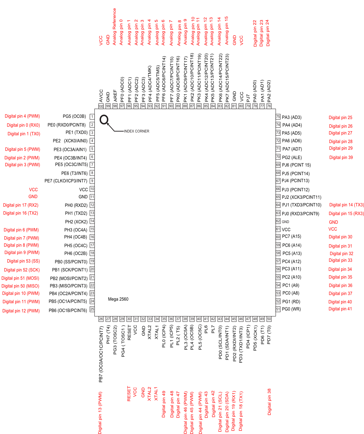
The source SVG file is also available for download: PinMapping2560.zip
Arduino Mega 2560 PIN mapping table
Pin NumberPin NameMapped Pin Name
1PG5 ( OC0B )Digital pin 4 (PWM)
2PE0 ( RXD0/PCINT8 )Digital pin 0 (RX0)
3PE1 ( TXD0 )Digital pin 1 (TX0)
4PE2 ( XCK0/AIN0 ) 
5PE3 ( OC3A/AIN1 )Digital pin 5 (PWM)
6PE4 ( OC3B/INT4 )Digital pin 2 (PWM)
7PE5 ( OC3C/INT5 )Digital pin 3 (PWM)
8PE6 ( T3/INT6 ) 
9PE7 ( CLKO/ICP3/INT7 ) 
10VCCVCC
11GNDGND
12PH0 ( RXD2 )Digital pin 17 (RX2)
13PH1 ( TXD2 )Digital pin 16 (TX2)
14PH2 ( XCK2 ) 
15PH3 ( OC4A )Digital pin 6 (PWM)
16PH4 ( OC4B )Digital pin 7 (PWM)
17PH5 ( OC4C )Digital pin 8 (PWM)
18PH6 ( OC2B )Digital pin 9 (PWM)
19PB0 ( SS/PCINT0 )Digital pin 53 (SS)
20PB1 ( SCK/PCINT1 )Digital pin 52 (SCK)
21PB2 ( MOSI/PCINT2 )Digital pin 51 (MOSI)
22PB3 ( MISO/PCINT3 )Digital pin 50 (MISO)
23PB4 ( OC2A/PCINT4 )Digital pin 10 (PWM)
24PB5 ( OC1A/PCINT5 )Digital pin 11 (PWM)
25PB6 ( OC1B/PCINT6 )Digital pin 12 (PWM)
26PB7 ( OC0A/OC1C/PCINT7 )Digital pin 13 (PWM)
27PH7 ( T4 ) 
28PG3 ( TOSC2 ) 
29PG4 ( TOSC1 ) 
30RESETRESET
31VCCVCC
32GNDGND
33XTAL2XTAL2
34XTAL1XTAL1
35PL0 ( ICP4 )Digital pin 49
36PL1 ( ICP5 )Digital pin 48
37PL2 ( T5 )Digital pin 47
38PL3 ( OC5A )Digital pin 46 (PWM)
39PL4 ( OC5B )Digital pin 45 (PWM)
40PL5 ( OC5C )Digital pin 44 (PWM)
41PL6Digital pin 43
42PL7Digital pin 42
43PD0 ( SCL/INT0 )Digital pin 21 (SCL)
44PD1 ( SDA/INT1 )Digital pin 20 (SDA)
45PD2 ( RXDI/INT2 )Digital pin 19 (RX1)
46PD3 ( TXD1/INT3 )Digital pin 18 (TX1)
47PD4 ( ICP1 ) 
48PD5 ( XCK1 ) 
49PD6 ( T1 ) 
50PD7 ( T0 )Digital pin 38
51PG0 ( WR )Digital pin 41
52PG1 ( RD )Digital pin 40
53PC0 ( A8 )Digital pin 37
54PC1 ( A9 )Digital pin 36
55PC2 ( A10 )Digital pin 35
56PC3 ( A11 )Digital pin 34
57PC4 ( A12 )Digital pin 33
58PC5 ( A13 )Digital pin 32
59PC6 ( A14 )Digital pin 31
60PC7 ( A15 )Digital pin 30
61VCCVCC
62GNDGND
63PJ0 ( RXD3/PCINT9 )Digital pin 15 (RX3)
64PJ1 ( TXD3/PCINT10 )Digital pin 14 (TX3)
65PJ2 ( XCK3/PCINT11 ) 
66PJ3 ( PCINT12 ) 
67PJ4 ( PCINT13 ) 
68PJ5 ( PCINT14 ) 
69PJ6 ( PCINT 15 ) 
70PG2 ( ALE )Digital pin 39
71PA7 ( AD7 )Digital pin 29
72PA6 ( AD6 )Digital pin 28
73PA5 ( AD5 )Digital pin 27
74PA4 ( AD4 )Digital pin 26
75PA3 ( AD3 )Digital pin 25
76PA2 ( AD2 )Digital pin 24
77PA1 ( AD1 )Digital pin 23
78PA0 ( AD0 )Digital pin 22
79PJ7 
80VCCVCC
81GNDGND
82PK7 ( ADC15/PCINT23 )Analog pin 15
83PK6 ( ADC14/PCINT22 )Analog pin 14
84PK5 ( ADC13/PCINT21 )Analog pin 13
85PK4 ( ADC12/PCINT20 )Analog pin 12
86PK3 ( ADC11/PCINT19 )Analog pin 11
87PK2 ( ADC10/PCINT18 )Analog pin 10
88PK1 ( ADC9/PCINT17 )Analog pin 9
89PK0 ( ADC8/PCINT16 )Analog pin 8
90PF7 ( ADC7 )Analog pin 7
91PF6 ( ADC6 )Analog pin 6
92PF5 ( ADC5/TMS )Analog pin 5
93PF4 ( ADC4/TMK )Analog pin 4
94PF3 ( ADC3 )Analog pin 3
95PF2 ( ADC2 )Analog pin 2
96PF1 ( ADC1 )Analog pin 1
97PF0 ( ADC0 )Analog pin 0
98AREFAnalog Reference
99GNDGND
100AVCCVCC

Friday, April 18, 2014

pan / tilt unit for pi

This can be done with different servos, etc, from scratch, but this is a nice unit to have as a starting point.

lifted from the following blog entry:

http://blog.dawnrobotics.co.uk/2013/10/using-the-dagu-pantilt-kit-with-the-raspberry-pi/

Using the Dagu Pan/Tilt Kit with the Raspberry Pi

The Pan/Tilt kit that we sell, developed by Dagu with the guys over at Let’s Make Robots, is a great way to mount mobile sensors on your robotic projects. In this tutorial we look at how you can control the Pan/Tilt kit with a Raspberry Pi and the Python programming language.


Required Materials and Equipment

Assembly

In order to control the servos of the pan/tilt kit with the Pi, we need to provide the servos with power, and connect their signal lines to GPIO pins on the Pi. Nearly all RC servos have the same wiring layout, although the colours may vary slightly. On the pan/tilt servos, the red (middle) wire is Vcc, the brown wire is Ground and the orange wire is the signal wire.
Connect the servos to the Pi as shown in the circuit diagram below. To begin with, we’d recommend that you get the servos working before you fully assemble the Pan/Tilt kit, as this way you can work out where the centre points of the servos are.
Circuit Diagram
Circuit Diagram – Made using Fritzing
 
External Servo Power
External Servo Power – Diagram made using Fritzing
As the the servos in the Dagu pan/tilt kit don’t require much current, we can power them from the 5V line of the Pi. If you’d prefer to power them from another power supply, or if you’re using different servos that require more current, or a higher voltage, then you can modify the circuit, as shown in this image.

Understanding Servo Motors

Unlike standard DC electric motors, which turn continuously at a given speed, servo motors contain control circuitry which is constantly trying to drive the servo motor to a set angle. Most servo motors are given their target angle by sending a Pulse Width Modulated (PWM) signal along their signal wire. A PWM signal consists of a pulse that repeats at a fixed frequency (usually close to 50Hz for a servo motor), the width of the pulse determines the angle that that we want the servo to move to.
Most servos will be centred with a pulse width of approximately 1500μs, and then turn left or right with smaller or bigger pulse widths. The minimum and maximum allowable pulse widths vary from servo to servo but are usually close to 800μs and 2200μs respectively. You should avoid trying to move a servo beyond its minimum and maximum limits, as this can damage the servo.

Controlling the Pan/Tilt Kit with Python

Once you’ve assembled the circuit, you can control the servos using this Python script. This script requires the RPIO Python library, which can be installed with the following steps
sudo apt-get install python-dev python-pip
sudo pip install RPIO
To use the script run
sudo python py_pan_tilt_control.py
The script will then sit in a loop, waiting for one of 3 commands. A ‘p’ will move the pan servo, ‘t’ will move the tilt servo, and ‘e’ will run an exploration animation, scanning the pan/tilt head back and forth. You can specify either an angle in degrees, or a pulse width in μs for the ‘p’ and ‘t’ commands by putting a number straight after them (no space). The program treats any number less than 500 as an angle in degrees, and all other numbers and a pulse width. As an example
: p90 - Will move the pan servo to 90 degrees
: p2000 - Will set the pan servo's pulse width to 2000μs
: t50 - Will set the tilt servo to 50 degrees
: e - Will the start the exploration animation
The script is a bit too long to explain in detail, but the important bit occurs on lines 144 to 151
?
142
143
144
145
146
147
148
149
150
151
#-----------------------------------------------------------
# Create ServoPWM instances to control the servos
panServoPWM = ServoPWM( PAN_PWM_PIN,
    minAnglePulseWidthPair=( 45.0, 1850 ),
    midAnglePulseWidthPair=( 90.0, 1400 ),
    maxAnglePulseWidthPair=( 135.0, 1000.0 ) )
tiltServoPWM = ServoPWM( TILT_PWM_PIN,
    minAnglePulseWidthPair=( 45.0, 1850 ),
    midAnglePulseWidthPair=( 90.0, 1500 ),
    maxAnglePulseWidthPair=( 180.0, 500.0 ) )
This allows you to specify 3 ( angle, pulse width ) pairs for each servo, that tell the script which pulse width corresponds to each angle. The script can then work out the pulse widths to use for other angles by using linear interpolation. The precise pulse widths will vary from servo to servo, so you should experiment with different pulse widths to get your servos turning accurately, and then adjust the ( angle, pulse width ) pairs accordingly.
Once you have your servo motors turning accurately, you can then finish assembling your pan/tilt kit. This approach takes much less time than hurriedly assembling the pan/tilt kit when you first get it, and then having to take it apart again to get it moving accurately, which was our initial approach. :)
In order to hold our pan/tilt kit steady as it moved, we mounted the complete circuit onto a bit of foamboard.
Assembled Circuit
Assembled Circuit

Taking Things Further

Pan/Tilt Kit with Camera
With the pan/tilt kit up and running, you can now mount sensors on it, and give them a much wider field of view than they would have if they were just mounted statically. The obvious sensor to mount for the Raspberry Pi is the camera, and we’ll hopefully have a look at using the camera with the pan/tilt kit in a future post.


Thursday, April 17, 2014

Two interesting bits to look at, omxplayer and fm transmission direct from clocks on Pi board


The Pi board can be set up to do FM broadcasts and an example is here:

http://makezine.com/projects/raspberry-pirate-radio/

Another article mentioned a media player that can be used when on the Pi in text mode, omxplayer

Also here is essentially an Arduino Uno which lives on the top of a Pi GPIO.

https://www.youtube.com/watch?v=GBeTOGnuUMM

board purchase / support site is here:

http://www.dawnrobotics.co.uk/pi-co-op-raspberry-pi-arduino-add-on-board/

£16.99, obviously from UK.


Friday, April 4, 2014

Raspberry pi i2c and spi bus notes


I ran across some notes about using i2c with the pi.  For my version, debian_version 7.0, Wheezy this page describes how to enable the access to the controller and install a simple program to access the ic chip

BC2708 it would appear.

http://www.cooking-hacks.com/forum/viewtopic.php?f=37&t=3512

This example is for a board which adapts arduino shields to the Pi, so you will get nowhere if not using a board with the chip attached.


1. Install i2c-tools on your Pi:
Code:
sudo apt-get install python-smbus
sudo apt-get install i2c-tools


2. If you have Raspbian, check /etc/modprobe.d/raspi-blacklist.conf and comment "blacklist i2c-bcm2708" by running sudo nano /etc/modprobe.d/raspi-blacklist.conf and adding a # (if its not there).
If you're running Wheezy you will need to
add the following lines to /etc/modules file
i2c-dev
i2c-bcm2708

3. Run i2cdetect (You need to specify the i2c bus where the ADC is attached, there are different for Rev1 and Rev2). THE BRIDGE MUST BE ATTACHED TO YOUR RASPBERRY PI.
Code:
# For Raspberry Pi rev2
sudo i2cdetect -y 1

#For Raspberry Pi rev1
sudo i2cdetect -y 2


Monday, March 24, 2014

xbee notes

Nice page with list of things you can do wrong

http://www.faludi.com/projects/common-xbee-mistakes/

High power xbee

http://www.soselectronic.com/?str=1128 

Xbee Pro 868

With XBee-PRO 868 you have 40 km within reach

If you´re searching for an RF communication module with a long range, you´re on the right address. More precisely said – 40 km at line-of-sight outdoor, or 550m indoor.
XBee technology enables to transfer data from various sources, mainly in industry – for example data from various sensors, controlling of technology and similar. XBee-PRO 868 from DIGI International (Maxstream) uses SRD G3 868 MHz band (869,525 MHz) and has a software selectable output power in the 1 - 315mW range.

Advantages / Features:

  1. powerful XBee module
  2. simple to use topology
  3. line-of sight range up to 40 km (outdoor) / 550m indoor and in urban conditions
  4. 1 to 315 mW (0 až +25 dBm) output RF power
  5. receiver sensitivity: -112 dBm
  6. 24kbps RF data rate
  7. AES 128 bit data encryption
  8. 16 bit network ID
  9. low power consumption 3,3V/65-500 mA
  10. footprint common with other XBee modules types
Relatively high maximum output power provides to the module a very long range. This enables to use it in applications with long distances between particular points. XBee_PRO can be connected to your application via a standard 3.3V CMOS UART with 1.2 to 230.4 Kbps data rate. Various XBee modules from Digi International feature common footprint, that´s why they´re mutually exchangeable this adaptable to your application requirements. XBee-PRO 868 features 128 bit AES encryption and a 64 bitovou adress (network ID). They are usable for Point-to-Multipoint/Star or also Peer-to-peer topologies. An advantage is also an easy use - no further configuration is necessary. Available are multiple versions, type XBP08-DPSIT-024 has an RPSMA connector. Thanks to it, the module can be connected to various antennas.

Detailed information will provide you the XBP08-DPSIT-024 datasheet, overview of XBee-PRO 868 modules, as well as XBee/RF family comparison from company Digi International. In case of interest, please contact us at info@soselectronic.com

Xbee to wireshark article

http://www.freaklabs.org/index.php/Tutorials/Software/Feeding-the-Shark-Turning-the-Freakduino-into-a-Realtime-Wireless-Protocol-Analyzer-with-Wireshark.html


Sunday, March 23, 2014

Simple method of mounting SD card image partitions for testing

Frequently you will have an SD card with linux or other partitions and you will require a method to access them.

In the case of the shell script here, I had to dd images of sd cards and I wanted to start out with just diffing everything on the two cards at a file level

First you need to fdisk the image and get the offset of the partitions you need to get to.

then perform a mount -loop,option with an offset to the start of the partition.

If you are lucky, you won't need to specify an FS type as the mount software will figure that out.


root@jws2:/home/jws/work/pitbull2# cat mount.sh
#!/bin/bash

#root@jws2:/home/jws/work/pitbull2# fdisk ipfire-72-pitbull.img
#
#Command (m for help): p
#
#Disk ipfire-72-pitbull.img: 15.7 GB, 15719727104 bytes
#64 heads, 32 sectors/track, 14991 cylinders, total 30702592 sectors
#Units = sectors of 1 * 512 = 512 bytes
#Sector size (logical/physical): 512 bytes / 512 bytes
#I/O size (minimum/optimal): 512 bytes / 512 bytes
#Disk identifier: 0x00000000
#
#                Device Boot      Start         End      Blocks   Id  System
#ipfire-72-pitbull.img1   *          32      131071       65520    c  W95 FAT32 (LBA)
#ipfire-72-pitbull.img3          131072    30701567    15285248   83  Linux


mount -o loop,offset=$((131072 * 512)) ipfire-72-pitbull.img /mnt/reference/
mount -o loop,offset=$((131072 * 512)) mmcblk0.backup.compress /mnt/test/

diff -u -r /mnt/reference /mnt/test > diffout.txt


This illustrates not only the mount method but also the diff method.

The two images are both 16gb SD card image files.  You would also have to create the files in /mnt, or some other location upon which to mount the images.

Reference on loop mounting:

http://madduck.net/blog/2006.10.20:loop-mounting-partitions-from-a-disk-image/